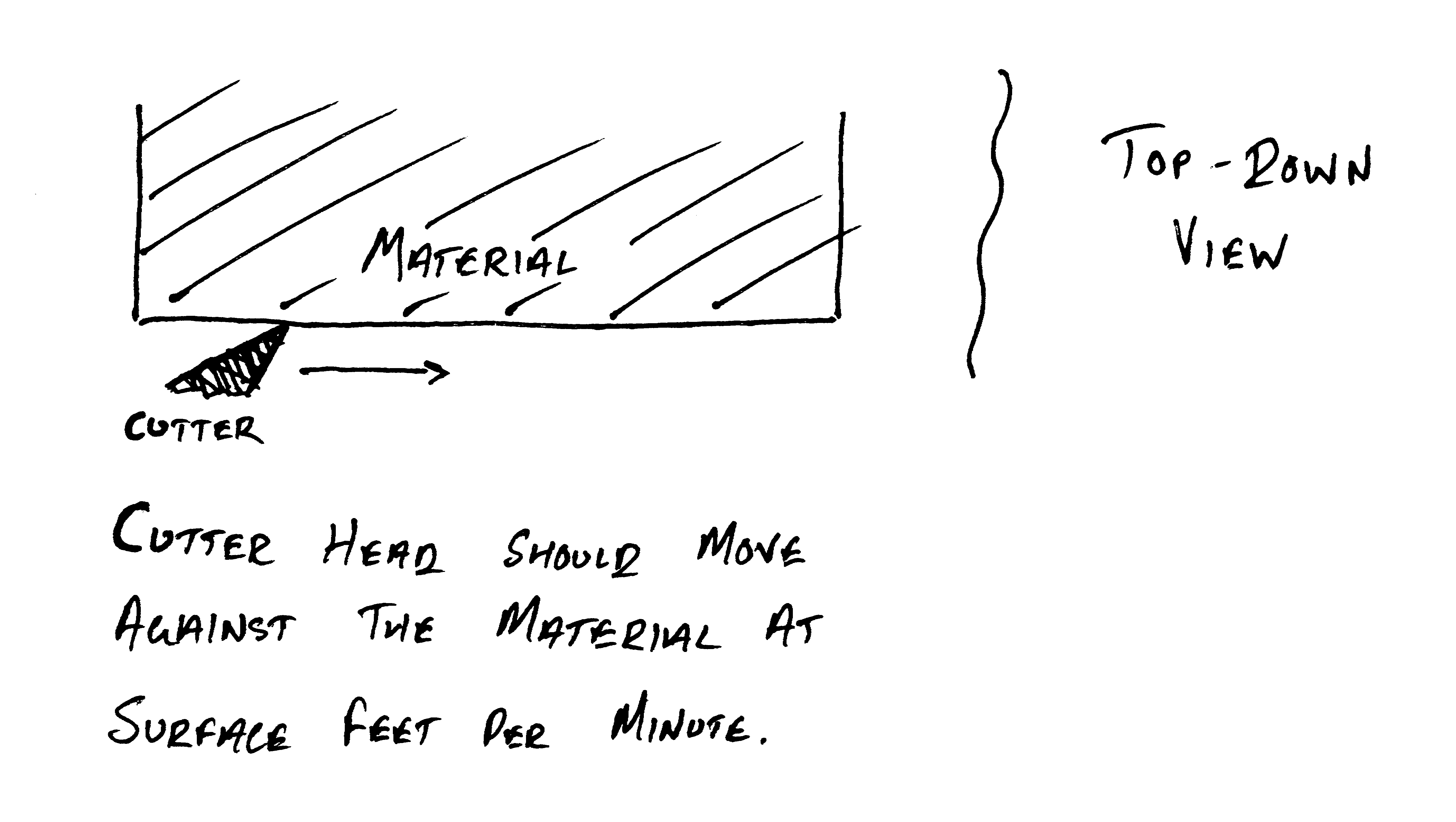
A geometric explanation of speed rates.
The mill speed formula confuses many engineering and machining students. Despite its universal application in drilling and milling operations on bridgeports and lathes, the underlying mechanism is often not explained, or not explained well. Choosing a speed can become a matter of punching numbers into an equation, and the rationale is never understood. As CNC technology becomes widespread, the formula may not be engaged with at all—even if CNC work is done in the shop; the material and tool are selected, and the computer does as it will.
The speed formula is sometimes given as:
where cutting speed is the surface feet per minute, and diameter is the tool diameter in inches per rotation. The cutting speed is drawn from a chart of material properties, and the tool being used is known. Variants for metric exist.
Alternatively, the formula is given as:
where 12 / pi reduces to an approximate 4 as in the first definition.
Use is straightforward enough—a calculation for cutting or drilling aluminum, which has a cutting speed of ~200sfm, with a 1/2” bit yields the spindle speed:
The mechanism of the formula is a geometric transformation of the cutting speed for use with a radial tool: the cutting speed is a property of the material being cut, expressed in feet per minute, and gives the speed that a (reasonably loaded) tool edge should move against the material. The formula yields the spindle speed, in rotations per minute, that will preserve this condition.
The 12 * variant obscures less of this transformation:
- On the top of the equation, multiplying the cutting speed by 12 converts the cutting speed to inches per minute, from feet per minute.
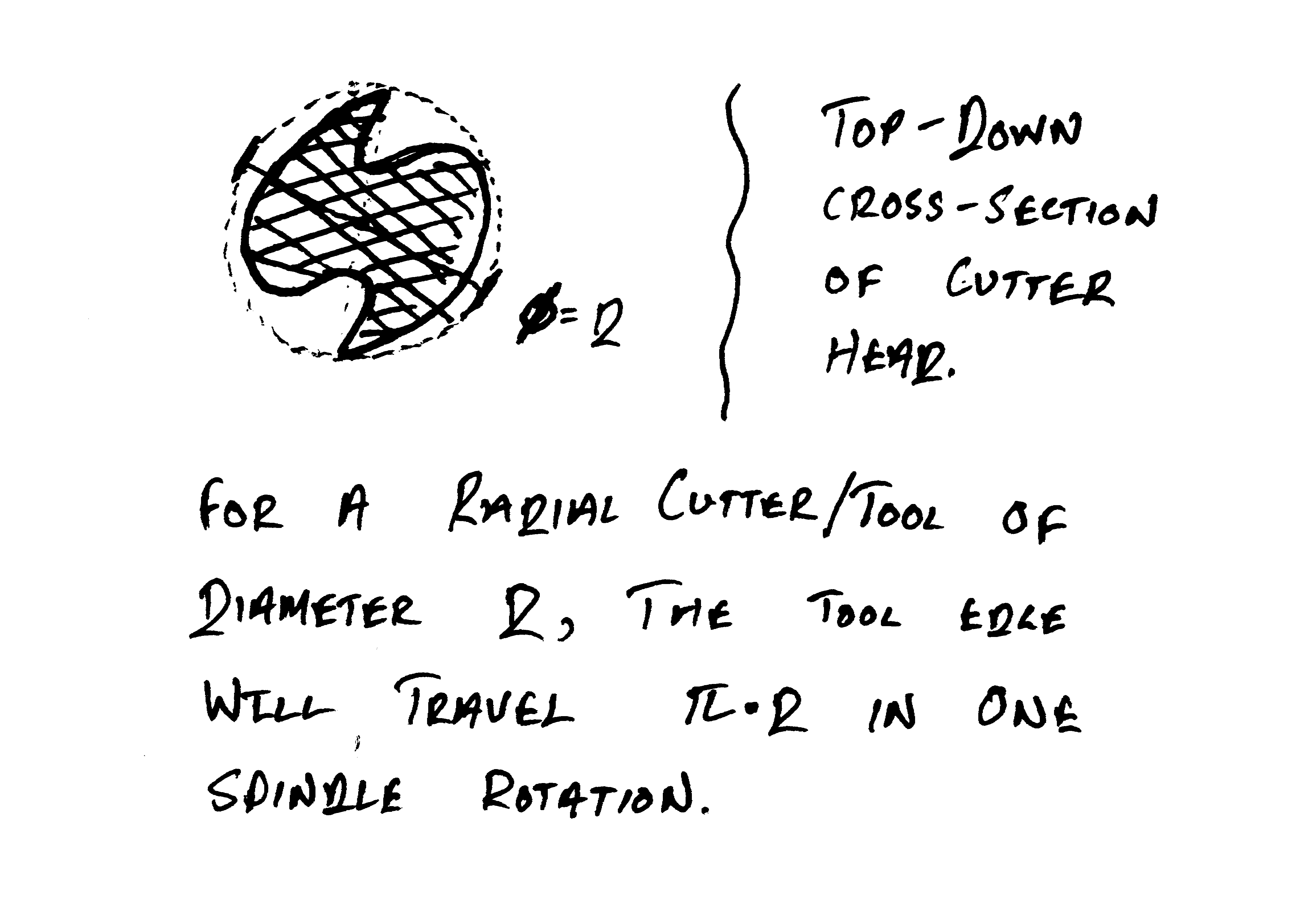
- On the bottom, pi * diameter calculates the circumference of the tool: this is the distance that a tool edge travels in one rotation of the spindle.
Dividing the inches per minute speed of the cutter head (top) by the edge distance travelled per rotation (bottom) gives the number of rotations per minute for these two properties.
With these unit labels, the formula is:
Pictorially:


By way of analogy, this equation and conversion is equivalent to finding how many rotations per minute a wheel must turn to sustain a vehicle’s given speed. (Aside from a fundamental reason that a vehicle go a certain speed, as a tool edge must.)
If a car is to go at 35mph, and has 27” tires:
35mph is converted to inches per minute:
This result is divided by the circumference to yield:
Still to do:
- add details on feed rates
- modifications for chip load and tool load
- modifications for tool material, cutter angles, and flutes per tool.


