Notes from taking apart a Shimano Nexus 8 Speed Hub, and understanding how it works.
Teaching Notes on Nexus Hubs
Overview of repairs
| Repair | Difficulty | Overview |
|---|---|---|
| Shift cable adjustment or replacement | 1 | Check the distance from the housing end to the fixing bolt, and check the yellow mark alignment in gear 4 |
| Cog replacement | 1 | Remove the cassette joint, then pry loose the snap ring holding it in place. Note the inward/outward orientation of the cog. |
| Left-side cup/cone service | 1 | Unscrew the nut and dustcap seal on the left side. The locking nut, cone, and bearing cage are the same as a typical cup/cone bearing. Note that the hub body can lift up and out while the locking nut and cone are removed. |
| Internals relubrication | 1 | As with a left-side cup/cone service, remove the left-side dustcap and cone. Then lift the shell up, and clean then dunk the insides in oil or spread grease over the moving parts. The internals can be separated into the carrier and driver/axle by removing the c-clip on the left end of the axle. |
| Right-side cup/cone service | 2 | With the cassette, cog, and shell removed, separate the driver and carrier by removing the axle c-clip. Remove the washer, lock nut, and cassette shift key adapter from the axle, outside the driver. This exposes the internal keyway. With the driver supported in a vice (but not the axle’s fixed sun gear), hammer the cone removal tool into the keyway. This will remove the right side cone, and separate the driver from the axle. After putting grease and the bearings back, gently hammer the cone back into place. |
| Driver service | 2 | Driver service is straightforward after right-side cone service. After removing the driver body, the clutch spring will float. The driver clutch comes off the axle through a winding path. During reassembly, seat the clutch tabs into grooves in the axle’s cup. The spring tapers up. |
| Carrier service | 3 | Disassemble in this order: snap ring holding the reduction ring gear in place; remove the snap ring holding the planetary gear pins in place; planetary gear pins for both the main and reduction gears (the reduction pins slide down through the same relief); reduction planetary gears out; lift the main ring gear off; main planetary gears out. Reassembly order is the same, with care towards gear timing and alignment needed. The axle support keyway washer must have its smooth side facing the drive side. |
| Axle service | 4 | Too complicated to explain here! |
Basic Anatomy of the Nexus 8
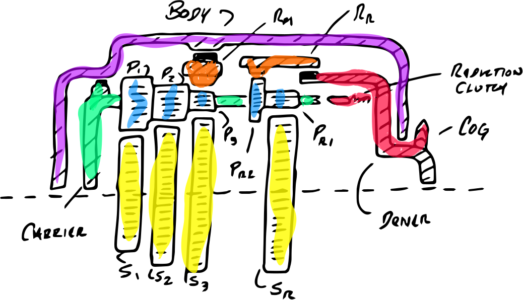
purple: the hub body
The hub body or shell rotates around the axle, and is the power output of the system: the spokes and wheel connect to it. The shell also seals and protects the gears and other internal mechanisms from the elements. Although these details are not drawn, the hub provides some structure, with a bearing set between it and the axle on the left side of the hub, and between it and the driver on the right side of the hub. There are black dust caps on both sides, the right side being much larger.
red: gear cog and driver
The driver is the power input to the system. The driver takes input from the cog and chain: this is where the drive power enters the internal hub. This power is passed onward through one of two routes: directly through the planet carrier when the driver clutch is engaged, and indirectly through the reduction gear when the driver clutch is disengaged.
yellow: sun gears
The four sun gears for the fixed component in two planetary gear sets. The one on the right, SR, is fixed to the axle, and does not move. The left three, S1, S2, and S3, are selectively fixed when locking pawls (not drawn) extend in specific gears.
blue and green: planetary gears and carrier
The planet carrier and its planetary gears rotate around the axle. There are two sets of planetary gears (blue) that rotate on pins inside the planet carrier (green). The right set is part of the reduction gear, which reduces the input speed. The left set is a series of multiplication gears, which increase the input speed; there are three, which are selected in different gears.
orange: ring gears
There are two ring gears in the drivetrain. The one on the right, RR, is part of the reduction gear ring, and transfers power between the driver and the planet carrier. The one of the left, RM, is part of the main gearset. This ring gear transfers power from the planet carrier to the hub shell body, through a roller clutch.
Axle and Control Sleeve
The axle is not drawn here. It is fixed to the frame of the bike, and does not rotate. One sun gear, SR, is fixed to the axle. The other sun gears spin freely, unless they are locked to the axle. This happens as pawls lock each sun gear, S1, S2 and S3, in different gears. These pawls are raised by a control sleeve as it rotates around the axle.
System Power flow
Driver and Reduction Clutch
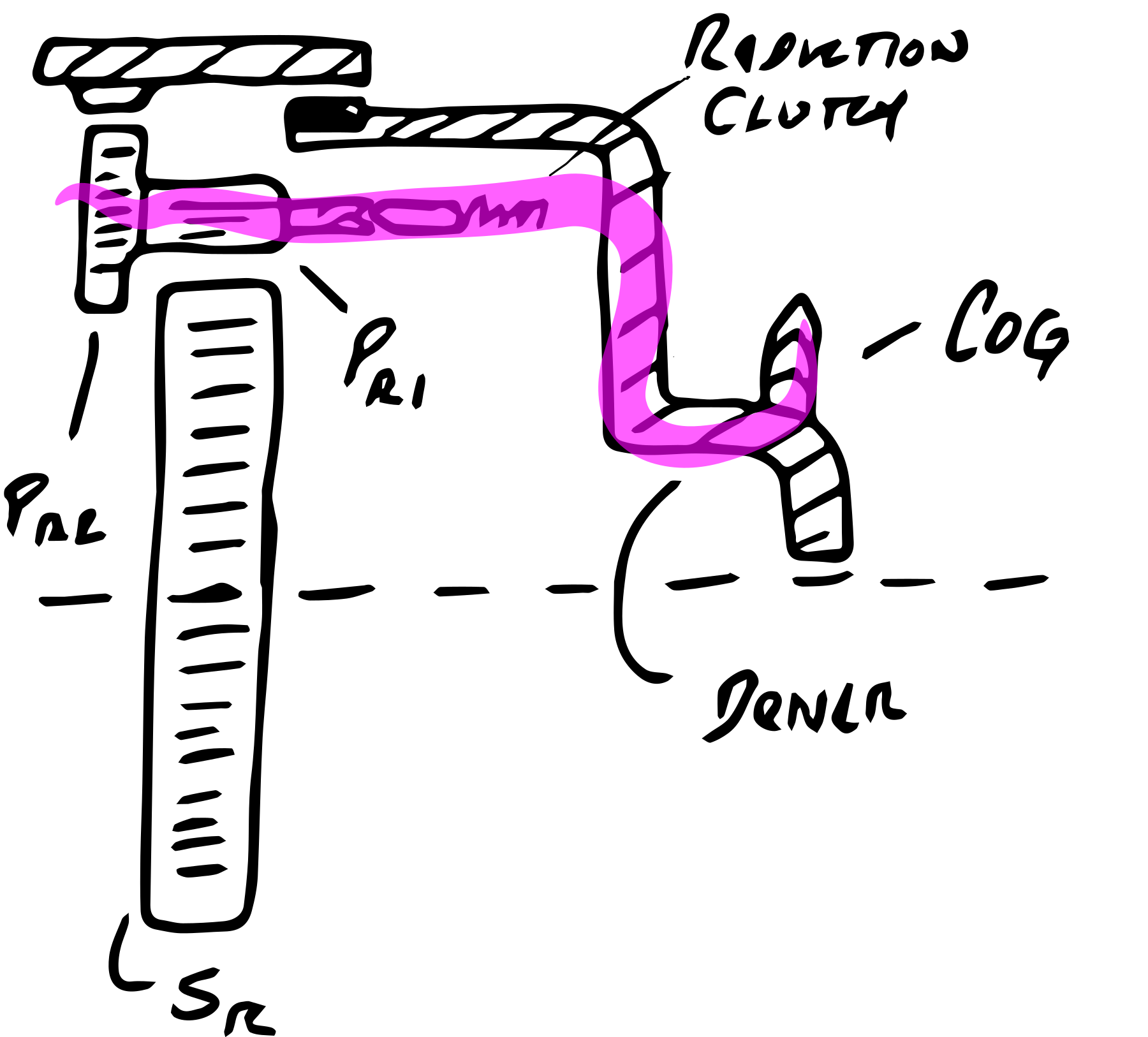
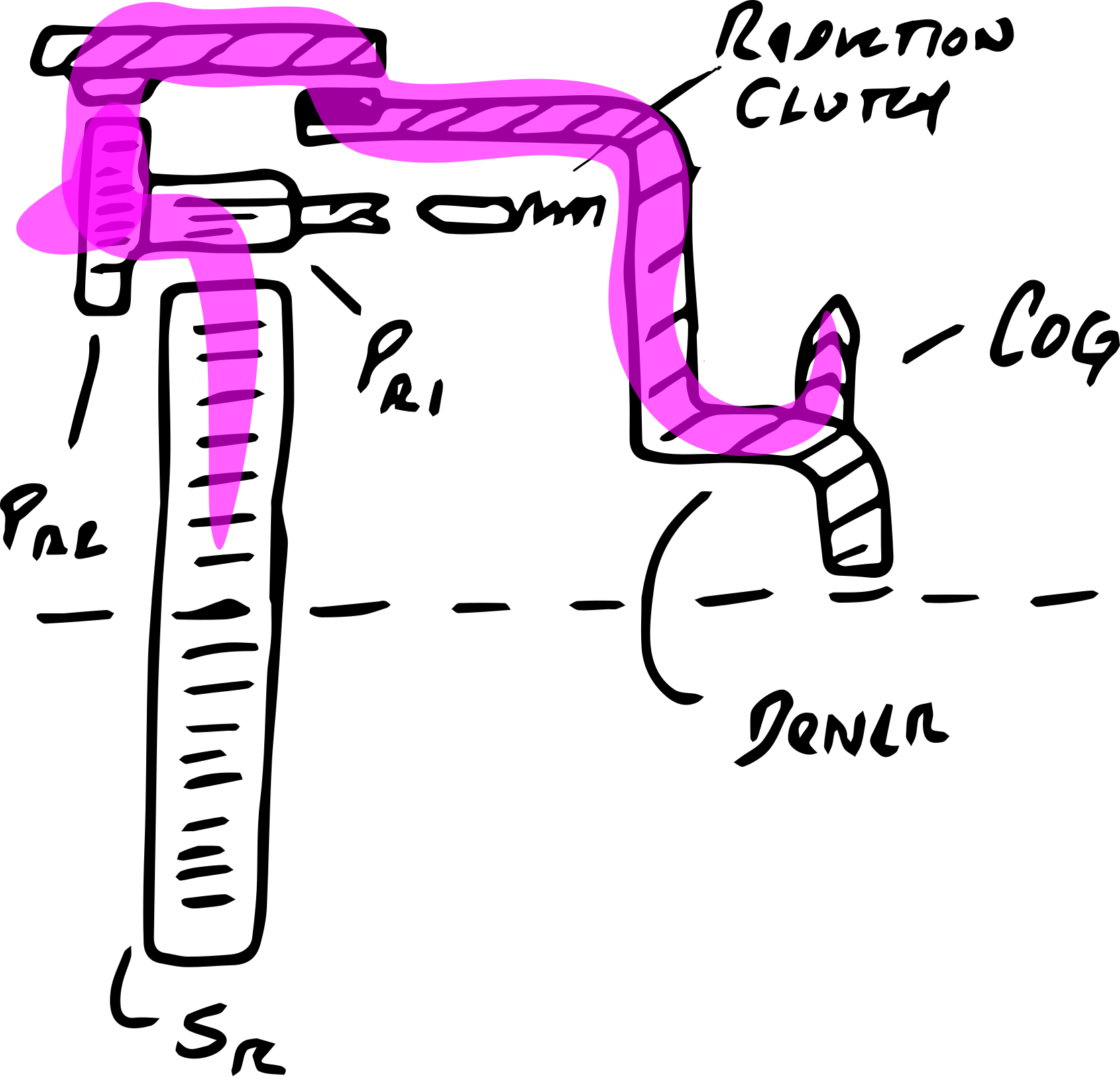
Power enters the hub as the chain drives the cog, which is mounted on the driver. The driver passes this power along to the planet carrier through two routes:
- Direct drive: when the reduction (bypass) clutch is engaged, drive power flows directly to the planetary carrier.
- Reduction drive to the planet carrier: when the reduction (bypass) clutch is not engaged, drive power flows through the ring gear, RR, instead through the roller clutch on the driver body. This drives the planetary gears around the fixed sun gear on the axle, reducing the drive speed into the planet carrier.
Main Gearset
After the power flows reduction or direct drive mechanisms, it enters the planet carrier. It leaves the planet carrier through one of four ways.
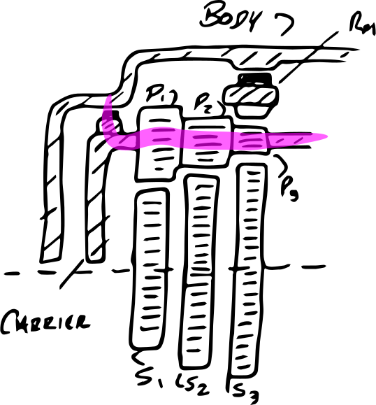
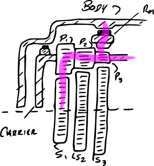
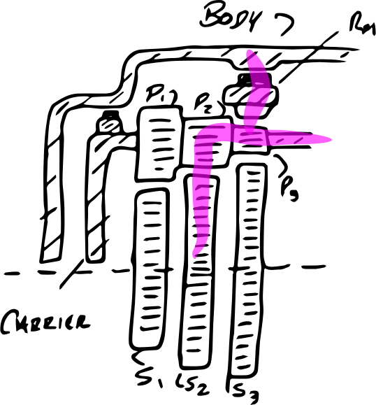
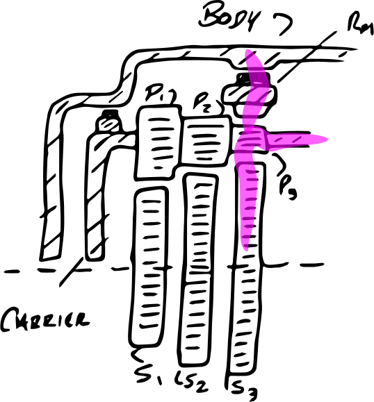
The first configuration ignores the three planetary gears, and drives the hub using a roller clutch on the end of the base. The other three configurations lock each sun gear. This engages the planetary gears, which drive the ring gear. The ring gear drives the hub body, through another roller clutch.
Putting it all together
These drawings show the entire drivetrain, with both the reduction gear and main gearset working together.
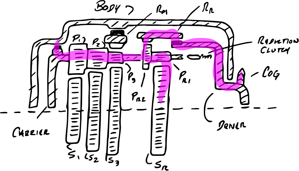
In first gear, the reduction gear is engaged, and the carrier drives the hub body directly through its roller clutch.
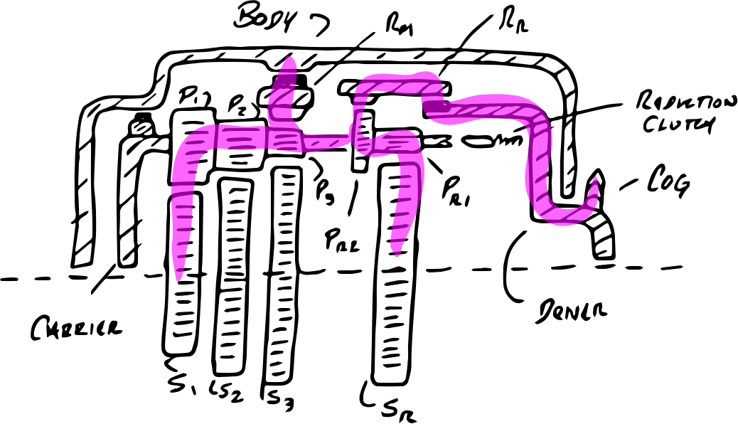
In second gear, the reduction gear is still engaged, and the carrier drives the hub body through its first sun gear. The third and fourth gears use S2 and S3 to step through higher gears (not drawn).
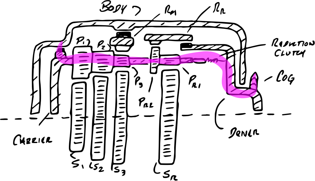
In fifth gear, the reduction (bypass) clutch drives the planet carrier directly, so the planet carrier rotates at the same speed as the cog. As with first gear, the planet carrier drives the hub body directly with its roller clutch.
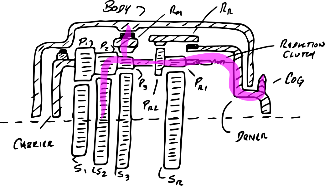
Gears six, seven, and eight are achieved through engaging the stepped increases of the main gearset. This drawing shows the power flow when the reduction (bypass) clutch is engaged, and the second sun gear is selected.
Gear Chart and States
Individual Gears
| Sun | Teeth | Planetary | Teeth | Ring | Tooth |
|---|---|---|---|---|---|
| S1 | 36 | P1 | 29 | RM | 78 |
| S2 | 42 | P2 | 18 | ||
| S3 | 48 | P3 | 14 | ||
| SR | 22 | PR1 | 14 | RR | 84 |
| PR2 | 22 |
Deriving the Simple and Compound Planetary Gear Ratios
The nexus hub always has the sun gear fixed. In the reduction stage, the ring gear is the input, and the planet carrier is the output. In the main stage, the planet carrier is the input, and the ring gear is the output. The reduction gear is a compound planetary gear, and the main gear is sometimes a simple and sometimes a compound gear.
With the planet carrier as input and the ring gear as the output:
- one rotation of the planet carrier will drive the ring gear one rotation, if the ring gear is fixed to the planet carrier by the gear teeth.
- every gear tooth on the sun gear rotates the planetary gear, which pushes the ring gear forward by one tooth
- in simple planetaries, the planetary gear count does not matter. In compound planetaries, this adds a multiplier ratio.
All together:
- in a simple planetary gear, the ring gear rotates by the ratio 1 + sun/ring
- in a compound planetary gear, the ring gear rotates by 1 + sun * planetary-ring / planetary-sun * ring
Gear Ratios
| Gear | Ratio |
|---|---|
| Reduction Gear: SR-PR1/PR2-RR | 0.527, from driver into planet carrier |
| Main 1st: S1-P1/P3-RM | 1.223, from planet carrier into hub body |
| Main 2nd: S2-P2/P3-RM | 1.420, from planet carrier into hub body |
| Main 3rd: S3-P3-RM | 1.615, from planet carrier into hub body |
Gear Chart and Mechanism States
| Gear | Reduction Gear | Carrier Direct Drive |
Sun Gear Locked | Output Gearing |
|---|---|---|---|---|
| 1 | y | y | None | 0.527 |
| 2 | y | n | S1 | 0.645 |
| 3 | y | n | S2 | 0.748 |
| 4 | y | n | S3 | 0.851 |
| 5 | n | y | None | 1.0 |
| 6 | n | n | S1 | 1.223 |
| 7 | n | n | S2 | 1.420 |
| 8 | n | n | S3 | 1.615 |